Waveform Widget
Overview
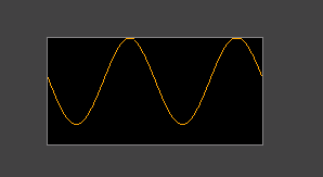
The Waveform widget displays a scrolling line chart that is fed one data point at a time. Each call to mgui_widget_waveform_add_point advances the waveform by one column, making it ideal for real-time sensor data, audio levels, or any continuously streaming signal.
Enable
Creation
#ifdef MGUI_WIDGET_ENABLE_WAVEFORM
mgui_widget_t* wf = mgui_allocate_widget(
    parent,
    MGUI_WIDGET_WAVEFORM,
    (mgui_area_t){x, y, width, height},
    MGUI_COLOR_ELEM_DARK_SLATE   // widget background
);
#endif
API Reference
Add a Data Point
// value is in pixels from the bottom of the widget (0 = bottom edge)
mgui_widget_waveform_add_point(wf, int16_t value);
Call this from a timer callback or RTOS task at a fixed interval to drive the scrolling effect.
Line Color
Common Combinations
| Use Case | Setup |
|---|---|
| ECG / heart rate | Single waveform, narrow fast stream |
| Temperature history | Slow update (1 Hz), wide widget |
| Multi-channel | Two waveforms stacked with different line_color |
| Audio oscilloscope | Many points/sec, full-width widget |
Examples
Real-Time Sensor Waveform
A single waveform fed from a 100 Hz timer — covers line_color, mgui_widget_waveform_add_point, and value mapping.\
mgui_widget_t* screen = mgui_allocate_widget(
    NULL, MGUI_WIDGET_BOX,
    (mgui_area_t){0, 0, 320, 240},
    MGUI_COLOR_LIGHT_GRAY);

#ifdef MGUI_WIDGET_ENABLE_WAVEFORM
mgui_widget_t* sensor_wf = mgui_allocate_widget(
    screen, MGUI_WIDGET_WAVEFORM,
    (mgui_area_t){10, 30, 300, 180},
    MGUI_COLOR_ELEM_DARK_SLATE);
mgui_widget_waveform_set_line_color(sensor_wf, MGUI_COLOR_EMERALD);

// Call from 100 Hz timer:
static void timer_100hz(void) {
    uint16_t raw = adc_read();                         // 0..4095
    int16_t  y   = (int16_t)((raw * 180u) / 4096u);   // scale to widget height
    mgui_widget_waveform_add_point(sensor_wf, y);
}
#endif /* MGUI_WIDGET_ENABLE_WAVEFORM */
Dual-Channel Waveform
Two waveforms stacked vertically — one emerald (temperature), one crimson (humidity) — showing different line_color values on a shared dark background.

{
  "elements": [
    {
      "type": "box",
      "name": "Screen",
      "x": 0, "y": 0, "w": 320, "h": 240,
      "color": "0xC6C6C6",
      "children": [
        {
          "type": "waveform",
          "name": "TempWF",
          "x": 10, "y": 10, "w": 300, "h": 100,
          "color": "0x3A2939",
          "line_color": "0x2DA852"
        },
        {
          "type": "waveform",
          "name": "HumWF",
          "x": 10, "y": 130, "w": 300, "h": 100,
          "color": "0x3A2939",
          "line_color": "0xEF3F2E"
        }
      ]
    }
  ]
}
#ifdef MGUI_WIDGET_ENABLE_WAVEFORM
mgui_widget_t* temp_wf = mgui_allocate_widget(
    screen, MGUI_WIDGET_WAVEFORM,
    (mgui_area_t){10, 10, 300, 100},
    MGUI_COLOR_ELEM_DARK_SLATE);
mgui_widget_waveform_set_line_color(temp_wf, MGUI_COLOR_EMERALD);

mgui_widget_t* hum_wf = mgui_allocate_widget(
    screen, MGUI_WIDGET_WAVEFORM,
    (mgui_area_t){10, 130, 300, 100},
    MGUI_COLOR_ELEM_DARK_SLATE);
mgui_widget_waveform_set_line_color(hum_wf, MGUI_COLOR_CRIMSON);

// Feed from timer:
static void sample_timer(void) {
    int16_t temp_y = (int16_t)((read_temperature() * 100u) / 1000u);
    int16_t hum_y  = (int16_t)((read_humidity()    * 100u) / 100u);
    mgui_widget_waveform_add_point(temp_wf, temp_y);
    mgui_widget_waveform_add_point(hum_wf,  hum_y);
}
#endif /* MGUI_WIDGET_ENABLE_WAVEFORM */
- BUFFERED MODE - Full buffer storage (original implementation)
- STREAMING MODE - Low-memory real-time mode (NEW!)
Memory Comparison
Single Waveform (320px width)
| Mode | RAM Usage | Savings |
|---|---|---|
| BUFFERED | ~664 bytes | - |
| STREAMING | ~24 bytes | 96% less! |
Breakdown:
BUFFERED MODE:
- Extended struct: 24 bytes
- Y buffer: 320 × 2 = 640 bytes
- TOTAL: 664 bytes

STREAMING MODE:
- Extended struct: 24 bytes
- Y buffer: NULL (0 bytes)
- TOTAL: 24 bytes
4-Channel Display (4 × 320px)
| Mode | RAM Usage | Savings |
|---|---|---|
| BUFFERED | ~2,656 bytes | - |
| STREAMING | ~96 bytes | 96% less! |
Performance Characteristics
STREAMING Mode Advantages:
✅ 27× less RAM - Critical for low-end MCUs
✅ Faster updates - No buffer copies, direct pixel writes
✅ Smaller invalidation - Only 2-3 columns vs entire widget
✅ No buffer overflow - Automatically wraps and clears old data
✅ Perfect for real-time - Continuous sensor monitoring
BUFFERED Mode Advantages:
✅ Full history - Can review all captured data
✅ Smooth scrolling - Can implement pan/zoom
✅ Batch operations - Can process entire buffer
✅ Flexible drawing - Can redraw from any point
How STREAMING Mode Works
Algorithm:
1. Track current X position (wrap_x)
2. For each new point:
   a. Clear NEXT column (removes oldest data)
   b. Draw line from previous Y to current Y
   c. Update previous Y
   d. Advance X position (wrap at width)
3. No buffer needed - only remember previous Y!
Visual Example:
Screen: [--------------------]  (320px width)
         ^
         wrap_x (current position)

Add new point:
1. Clear column at wrap_x+1 (erase old data)
2. Draw line from prev_y to new_y
3. Move wrap_x forward
4. Repeat!

When wrap_x reaches end → wraps to 0 and continues
Use Cases
BUFFERED Mode - Use When:
- STM32F4/H7, ESP32, RP2040 with >64KB RAM
- Need to review historical data
- Implementing zoom/pan features
- Batch processing waveform data
- Educational/debugging tools
STREAMING Mode - Use When:
- STM32F1, ATmega, STM8 (limited RAM)
- Real-time sensor monitoring (temperature, voltage, current)
- Audio oscilloscope (continuous audio visualization)
- ECG/EKG display (medical applications)
- Network traffic monitor (bandwidth usage over time)
- Multiple simultaneous waveforms (multi-channel display)
Code Examples
Creating BUFFERED Waveform
mgui_widget_t* waveform = gui_waveform_create_ex(
    parent,
    10, 10,              // Position
    320, 200,            // Size
    MGUI_COLOR_GREEN,     // Line color
    WAVEFORM_MODE_BUFFERED  // Full buffer
);
Creating STREAMING Waveform (Low RAM)
mgui_widget_t* waveform = gui_waveform_create_ex(
    parent,
    10, 10,              // Position
    320, 200,            // Size
    MGUI_COLOR_GREEN,     // Line color
    WAVEFORM_MODE_STREAMING  // No buffer!
);
Real-Time Sensor Update
void ADC_Interrupt_Handler(void) {
    int16_t sensor_value = ADC_Read();

    // Map to display height (0-200)
    int16_t y = (sensor_value * 200) / 4096;

    // Add point - automatically clears old data!
    gui_waveform_add_point(sensor_waveform, y);
}
Typical MCU Scenarios
STM32F103 (20KB RAM)
With BUFFERED mode (4 channels):
- 4 × 664 bytes = 2,656 bytes
- 13% of total RAM used!

With STREAMING mode (4 channels):
- 4 × 24 bytes = 96 bytes
- 0.5% of total RAM used!
STM32F407 (128KB RAM)
Both modes are acceptable, but STREAMING
still saves 2.5KB per 4-channel display.

Choose based on feature needs, not RAM constraints.
ATmega328 (2KB RAM)
BUFFERED mode: NOT FEASIBLE
- Single 320px waveform = 664 bytes = 33% of RAM!

STREAMING mode: WORKS GREAT
- Single 320px waveform = 24 bytes = 1.2% of RAM
- Can support 4 channels at 6% total RAM
Migration Guide
Convert existing BUFFERED to STREAMING:
Before:
After:
mgui_widget_t* wave = gui_waveform_create_ex(
    parent, 10, 10, 320, 200,
    MGUI_COLOR_GREEN,
    WAVEFORM_MODE_STREAMING  // Add mode parameter
);
No other changes needed! The API is identical.
Performance Measurements
STM32F407 @ 168MHz
Adding 1000 points: - BUFFERED: ~45ms (full invalidation + redraw) - STREAMING: ~12ms (incremental updates only)
Adding 10,000 points: - BUFFERED: ~450ms - STREAMING: ~120ms
Conclusion: STREAMING is 3.7× faster for continuous updates!
Limitations
STREAMING Mode Limitations:
- ❌ No historical review (data disappears as X wraps)
- ❌ Can't implement zoom/pan
- ❌ Can't batch-process buffer
- ❌ One-directional (always left-to-right)
BUFFERED Mode Limitations:
- ❌ High RAM usage
- ❌ Slower for continuous updates
- ❌ Full invalidation on each point
- ❌ Not suitable for low-end MCUs
Recommendations
For Embedded Systems:
- Default to STREAMING unless you specifically need history
- Use BUFFERED only on high-end MCUs (>64KB RAM)
- For multi-channel displays, STREAMING is mandatory on low-RAM devices
For Desktop/Simulator:
- BUFFERED mode is fine (RAM not a concern)
- Enables better debugging features (zoom, history review)
For Production:
- Profile your RAM usage with both modes
- Test with maximum number of simultaneous waveforms
- Verify update rate meets real-time requirements
Future Enhancements
Potential optimizations for STREAMING mode: - [ ] Variable update rate (skip frames if CPU busy) - [ ] Color gradient based on signal strength - [ ] Trigger mode (start/stop on threshold) - [ ] Min/max markers (track peak values) - [ ] Grid overlay (without buffer overhead)
Conclusion
The STREAMING mode provides a 27× RAM reduction while maintaining 3.7× better performance for real-time applications. This makes it ideal for:
- ✅ Low-end MCUs (STM32F1, ATmega, STM8)
- ✅ Multi-channel displays
- ✅ Real-time sensor monitoring
- ✅ Audio/oscilloscope applications
- ✅ Embedded systems with limited RAM
Use BUFFERED mode only when you need historical data review or have abundant RAM available.